
Network Topology
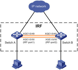
To increase the number of access interfaces and simplify the network topology, use XGE1/0/49 and XGE1/0/50 on Switch A and Switch B to form an IRF.
Configuration Steps
(1) Configuration of Switch A
# Configure IRF in the Device > Virtualization > IRF page, and the configuration steps are as follows.
- Basic configuration: Go to the details page of member device 1, and configure the new member number of the device as 2; in order to make the device elected as Master, configure the priority as 10.
- Bind IRF ports: Go to the details page of IRF interface 1 and bind IRF interface 1 to physical interfaces XGE1/0/49 and XGE1/0/50.
- Advanced configuration: Enable the auto-merge function and configure the domain number to 10.
# Activate the IRF port configuration. When activating, select Save Current Configuration and reboot the device so that the new member number can take effect.
(2) Configuration of Switch B
# Configure IRF in the Device > Virtualization > IRF page, and the configuration steps are as follows.
- Basic configuration: Go to the details page of member device 1, and configure the new member number of the device as 3.
- Bind IRF ports: Enter the details page of IRF interface 2 and bind IRF interface 2 with physical interfaces XGE1/0/49 and XGE1/0/50.
- Advanced configuration: Enable the auto-merge function and configure the domain number to 10.
# Activate the IRF port configuration, and select Save Current Configuration when activated.
# Connect interface XGE1/0/49 and XGE1/0/50 of Switch A to interface XGE1/0/49 and XGE1/0/50 of Switch B.
Key Configuration
The IRF physical ports and related restrictions supported by the device are related to the device model, please refer to the configuration guide corresponding to the device software version for details.
Verify the configuration
Login to the Web page of Switch A, and check the topology information in the "Device > Virtualization > IRF" page of Switch A. You can see that:
- There are member device 2 (Switch A) and member device 3 (Switch B) in the IRF, and they form neighbors with each other.
- The IRF interface is in the connected state.