M-LAG Networking, Terminal Under the M-LAG Cannot Ping the Device Address
- 0 Followed
- 0Collected ,1468Browsed

Network Topology
Devices and Versions: S10508 R7596P09
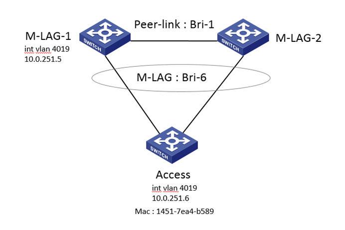
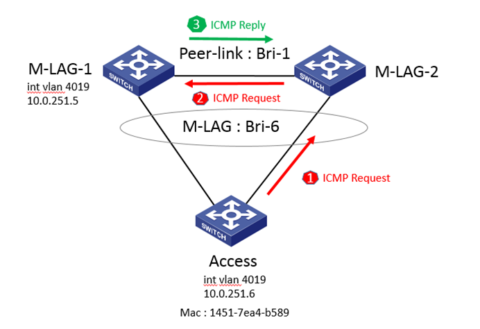
Networking: Two S10508 devices are used as M-LAG devices, without VLAN dual-active or VRRP gateway. One M-LAG device has the VLAN corresponding to the terminal, and the M-LAG interface is connected to the downstream device. The following figure shows a partial network diagram.
Problem Description
On-site M-LAG networking, VLAN dual-active or VRRP gateway is not enabled on the M-LAG device. The downstream device is connected to the M-LAG interface BAGG6 and VLAN 4019 is allowed on BAGG6. Only the M-LAG-1 device has the interface vlan-interface4019 address, which is 10.0.251.5. The M-LAG-2 device does not have a layer 3 virtual interface for VLAN4019. The address of int vlan 4019 on the downstream device is 10.0.251.6. Ping from the downstream device to 10.0.251.5 is not successful.
Process Analysis
This configuration on-site is not standard. Why does this non-standard configuration lead to connectivity issues?
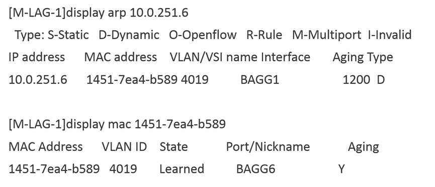
For the case of direct connectivity failure, we need to first confirm the ARP/MAC learning status. By checking the entries, we found that on the M-LAG-1 device, the ARP learning of the downstream device is on the peer-link interface, and the MAC learning is on the M-LAG interface.
In normal cases, ARP and MAC should be learned on the M-LAG interface for proper M-LAG forwarding. Let's review the synchronization process of ARP and MAC between the two M-LAG devices in the M-LAG networking:
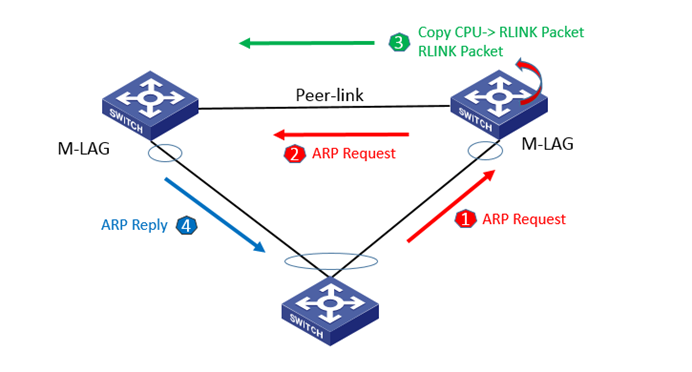
When the M-LAG interface of the M-LAG device receives an ARP request packet, it will flood a copy to the peer M-LAG device through layer 2 flooding. The ARP learning on the peer M-LAG device is on the Peer-link interface. At the same time, the received ARP request packet is sent to the platform via the rlink packet, synchronizing the ARP packet to the peer M-LAG device. At this time, the ARP on the peer M-LAG device is learned on the M-LAG interface, replacing the ARP learned on the peer-link interface as shown in the diagram below:
Unlike ARP synchronization packets, MAC synchronization in M-LAG synchronizes table entries. MAC table entries learned on the M-LAG interface of one device are directly synchronized to the M-LAG interface of the other device.
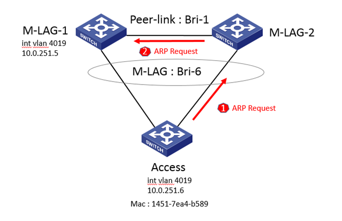
In the on-site troubleshooting environment, we performed ARP flow statistics on the devices and found that ARP packets enter the device from the M-LAG interface of M-LAG-2. Since M-LAG-2 does not have int vlan 4019, the ARP packets are not sent to the CPU and do not trigger rlink encapsulation synchronization. M-LAG-1 only receives ARP packets flooded from the peer-link interface through layer 2 broadcasting. Therefore, the outgoing interface for ARP on the M-LAG-1 device is the peer-link interface. However, MAC synchronization in M-LAG is based on table entries, so the MAC addresses of the downstream devices on M-LAG-1 and M-LAG-2 are learned on the M-LAG interface.
Next, we performed ICMP flow statistics on the devices and found that ICMP request packets from the downstream device can reach M-LAG-1 normally. However, when M-LAG-1 replies with ICMP reply packets, they are sent to the M-LAG-2 device through the peer-link interface, but M-LAG-2 does not forward the packets to the downstream access device. This is because ICMP packets are forwarded at layer 2 on the M-LAG-2 device, with the egress port being the M-LAG interface. Since M-LAG-2 determines that both selected M-LAG interfaces are present, the traffic received from the peer-link link is directly dropped and not sent out from the M-LAG interface.
Solution
Simply configure VLAN 4019's layer 3 virtual interface on both M-LAG devices.