M-LAG+VRRP Server Dual NIC Access Traffic Flooding
- 0 Followed
- 0Collected ,1381Browsed

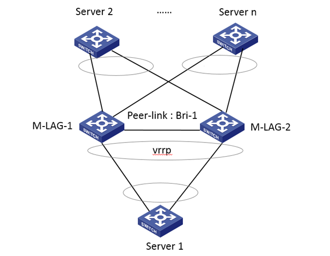
Network Topology
Devices and Versions: S6850 R6635
Networking: Two S6850 devices are configured with M-LAG+VRRP as the gateway for the server. The server is connected to the two M-LAG devices through primary and backup NICs respectively. There is no M-LAG aggregation interface configured on the M-LAG devices.
Problem Description
During on-site M-LAG+VRRP networking, two S6850 devices are configured with M-LAG+VRRP as the server gateway. The server is connected to the two M-LAG devices through primary and backup NICs respectively. No M-LAG aggregation interface is configured on the M-LAG devices, resulting in a single connection for the server. When accessing other servers using the backup NIC, Server1 cannot communicate with other servers, and there is a large amount of flooding traffic in the outbound direction on the M-LAG devices.
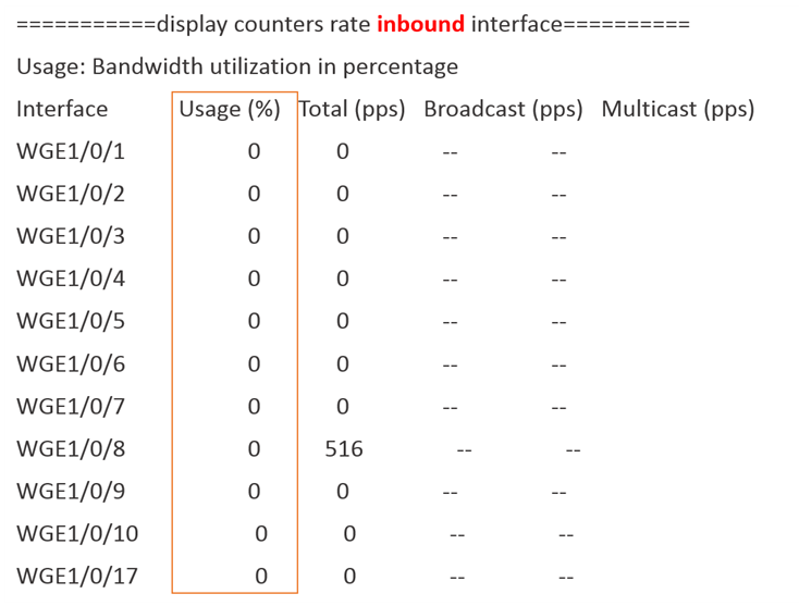
By checking the traffic on the interfaces of the backup device, it is found that there is almost no inbound traffic on interfaces WGE1/0/1 to WGE1/0/17:
However, the outbound traffic on these interfaces reaches 21%:
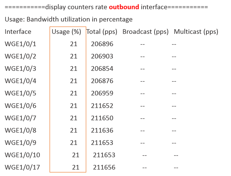
By capturing packets on these interfaces using outbound mirroring, it is found that the packets are all from Server1 accessing other servers, and the destination MAC address of the packets is the virtual MAC address of the VRRP gateway, indicating that the packets sent by Server1 are flooding out from other ports on the device.
Process Analysis
By checking the VRRP status on the device, it is found that the VRRP status is normal. In the M-LAG+VRRP networking, both M-LAG devices will distribute the VRRP virtual MAC address at the underlying layer. This means that when the device receives a packet with the destination MAC address being the VRRP virtual MAC address, it should be directly forwarded at layer 3 instead of flooding.
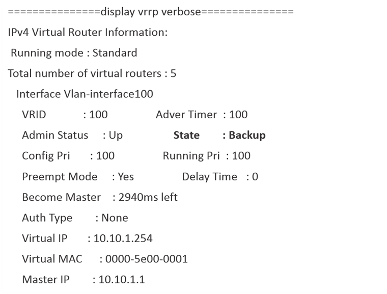
So why is the device flooding this part of the traffic?
By checking the distribution of the underlying virtual MAC address on both M-LAG devices, it is found that the main device has distributed the VRRP virtual MAC address at the underlying layer, while the underlying layer of the backup device does not have this hardware entry:
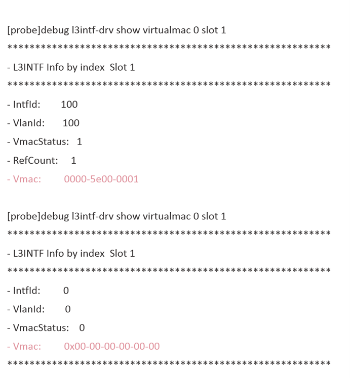
Since the backup device does not have the hardware entry for the VRRP virtual MAC address, when it receives a packet with the destination MAC address being the VRRP virtual MAC address sent by the backup NIC of Server1, it does not consider the destination MAC address as its own MAC address. Therefore, it does not follow the layer 3 forwarding process but uses layer 2 forwarding instead. Due to the lack of this MAC entry, flooding occurs at layer 2.
So why does the backup device not have the hardware entry for the VRRP virtual MAC address at the underlying layer?
In the on-site scenario where the server is connected through primary and backup NICs, which is equivalent to a pure single connection, and no M-LAG aggregation interface is configured on the device, there are the following limitations:
When the server is connected through primary and backup NICs (bond1), and the VLAN for the VRRP gateway is not configured with any M-LAG interface, a M-LAG aggregation group needs to be created, and the M-LAG aggregation interface needs to be configured to allow the VLAN to pass through.
For example, if VLAN interface 100 is configured with VRRP but no M-LAG aggregation interface is added to VLAN 100, unexpected unknown unicast traffic flooding may occur, and excessive flooding traffic may cause packet loss.
Solution
According to the device limitations, create a M-LAG aggregation interface and configure the aggregation interface to allow VLAN 100 to pass through. In the future, we plan to develop a dedicated command to optimize the limitations of this pure single connection scenario in M-LAG.