M-LAG Peer-Link Failure Causes the Main Device to Be MAD DOWN
- 0 Followed
- 0Collected ,1562Browsed

Network Topology
Devices and Versions: S12504G-AF R7624P15
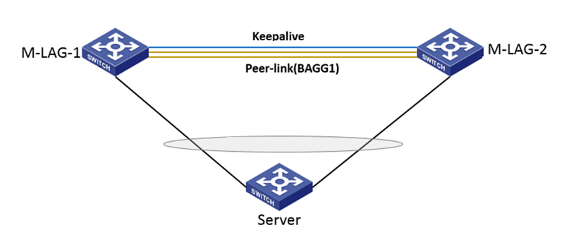
Networking: Two S12504G-AF devices are configured with M-LAG, and the server's primary and backup NICs are connected to the M-LAG devices respectively. No M-LAG interface is configured (same as the previous scenario of pure single connection). The following figure shows a partial networking diagram:
Problem Description
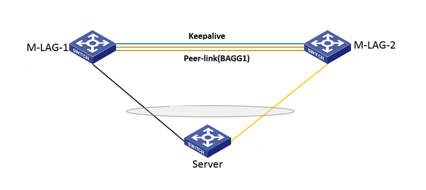
During on-site M-LAG networking, no VLAN dual-active or VRRP gateway is configured. The server's primary and backup NICs are connected to the two M-LAG devices, resulting in a pure single connection scenario. M-LAG-1 is configured as the main device and M-LAG-2 is configured as the backup device. However, due to a previous restart of M-LAG-1 and a previous main/backup switchover, the actual effective roles are M-LAG-2 as the main device and M-LAG-1 as the backup device, causing the traffic to reach the server's backup NIC.
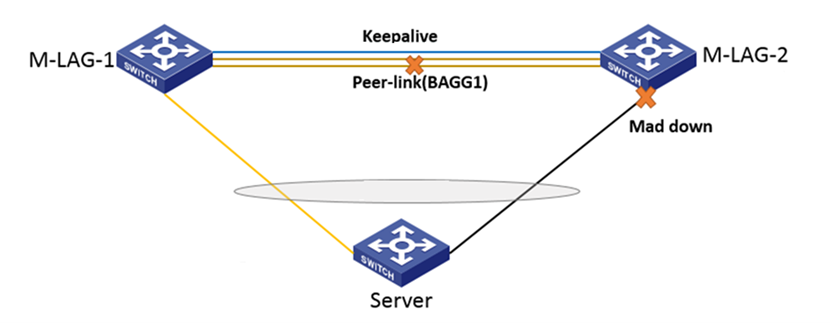
In this scenario, when the peer-link link fails and the keepalive link works normally, on-site service faults occur and are restored after a period of time. When the on-site engineer checks the service status, it is found that the service has switched from the backup NIC to the primary NIC, and the business interface of the originally effective M-LAG main device (i.e., M-LAG-2) is MAD DOWN.
Process Analysis
Due to the switchover of the server's primary and backup NICs, it is confirmed with the on-site engineer that when the server's primary and backup NICs are switched, the server needs to restore the business entries itself, which results in service interruption. Therefore, the direct cause of the on-site service fault is the switch of the server's primary and backup NICs, and the reason for the switch of the primary and backup NICs is that the business interface of M-LAG-2 is MAD DOWN.
At this point, there is a question: why is the device that is actually the main device (M-LAG-2) MAD DOWN when the peer-link fails?
Here, let's take a closer look at the fault handling mechanism of M-LAG. When the peer-link fails but the keepalive link works normally, it is indeed necessary to MAD DOWN the interface of the backup device. However, this backup device is the calculated backup device at that time, not the backup device before the fault occurred.
If we carefully review the official configuration guide, we can see the following explanation:
The triggering conditions for M-LAG character calculation include:
l
l
l
l
Pay attention here, my friends. When the peer-link fails and the keepalive link works normally, the roles of M-LAG-1 and M-LAG-2 devices should be recalculated. This means that after the peer-link fails on-site, the roles of M-LAG-1 and M-LAG-2 devices need to be recalculated based on the keepalive link. The role calculation rules are also detailed in the configuration manual:
When calculating device roles through peer link or Keepalive link interaction messages, compare the following factors in sequence:
1)
2)
3)
4)
5)
6)
According to these calculation rules, let's take a look one by one:
Full single hanging scene, both devices have no available M-LAG ports, so the first rule passes;
There are no devices with a "none" role or devices that are MAD DOWN before the failure, so the second and third rules are not satisfied;
Since the device health was not checked before the failure, the fourth rule is uncertain, but the entire system was running normally before the failure, so it is highly likely that both devices have no issues, i.e., the health value is 0;
M-LAG-1 is configured as the primary device with a higher role priority than M-LAG-2, so M-LAG-1 wins the fifth rule;
Since the roles of both devices can be determined based on the fifth rule, there is no need for comparison in the sixth rule;
Based on the above analysis, after the peer-link failure, there is a high possibility that M-LAG-1 will be calculated as the primary device, so it is normal for M-LAG-2, which is recalculated as the backup device, to be MAD DOWN;
From the above information, MAD DOWN of M-LAG will actually elect a backup device based on the role calculation rules, rather than simply MAD DOWN the interface with the role of the backup device that was effective before the failure;
Solution
M-LAG itself is a cross-device link aggregation. If there is a need for business interruption when switching on the business side, it is recommended to modify the networking to the form of M-LAG aggregation in a timely manner. If there is indeed a business requirement for full single hanging of M-LAG, it is recommended to ensure that the primary and backup devices of the business are consistent with the configured primary and backup devices of M-LAG, and also pay attention to the restriction mentioned earlier - create an M-LAG aggregation interface and configure the aggregation interface to allow the corresponding VLAN to pass through;