
Network Topology
Devices and Versions: S6805 R6616P01
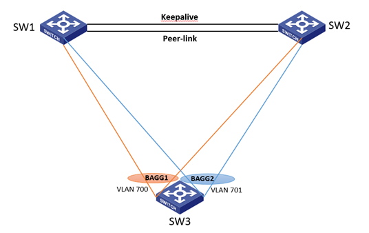
Networking: SW1 and SW2 are configured with M-LAG+VRRP at the site and are connected to downstream SW3 through M-LAG interfaces. The special thing is that SW1 and SW2 have two M-LAG interfaces respectively connected to SW3, allowing VLAN700 and VLAN701 to pass through. The gateway of SW3 is on the M-LAG system, as shown in the following figure:
Problem Description
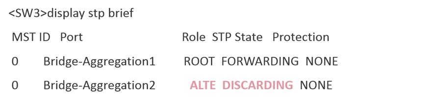
After the configuration is completed according to the figure, it is found that accessing the gateway of VLAN701 from SW3 through passBAGG2 is not reachable. Further investigation reveals that BAGG2 on SW3 is in STP blocking state:
Process Analysis
Let's review the processing mechanism of M-LAG+STP. M-LAG calculates the STP of M-LAG interfaces centrally, and the entire M-LAG system is an STP bridge with the STP bridge ID using the system MAC. At the site, this networking configuration seems to have no problem at first glance, but upon careful analysis, it can be seen that passBAGG1/2 on SW3 is connected to the M-LAG system, and the entire M-LAG system is an STP bridge. Abstractly, the networking configuration is as follows:
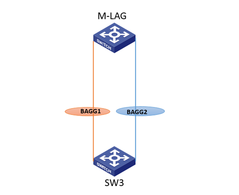
Doesn't it look like a physical loop? Therefore, it is normal for BAGG2 to be in STP blocking state, and the phenomenon at the site is also a normal phenomenon in this networking environment.
Solution
Due to the different VLANs allowed by the two aggregation groups, PVST can be used at the site to avoid the problem.